HVAC Load Calculations in Ontario: Heating, Cooling & Equipment Sizing
An HVAC load calculation is the engineering bridge between the building and the equipment schedule. Done properly, it explains when, where and why heating and cooling demand occurs—before capacity, airflow, hydronics, controls and electrical service requirements are committed.

Perimeter, core and orientation-specific zones can peak at different hours. The coincident system peak must preserve that diversity.
Temperature and moisture loads both matter. Equipment performance must be checked at the entering conditions used for the project.
The peak load informs equipment selection; it is not automatically the final scheduled capacity or nominal tonnage.
What an HVAC Load Calculation Actually Does
A load calculation estimates the rate at which heat must be added to or removed from a space under defined design conditions. It is the primary basis for sizing air systems, hydronic systems and plant components, including ducts, diffusers, air-handling units, coils, boilers, chillers, heat pumps, fans and pumps.
The result is not one universal number. A useful model preserves the relationship between space loads, zone loads, system loads and plant loads. Fan heat, duct gain or loss, ventilation, heat recovery and distribution effects can cause the equipment load to differ from the room load.
From building inputs to equipment selection
The calculation should retain the path from physical assumptions to the final schedule.
Floor-area ratios can be useful during feasibility planning, but they cannot see orientation, glazing, schedules, occupancy, ventilation, process loads or zoning. Use them to challenge a result, not to replace the calculation.
Heating and Cooling Are Different Design Problems
| Design aspect | Heating load | Cooling load |
|---|---|---|
| Primary drivers | Outdoor-to-indoor temperature difference, envelope heat loss, infiltration and required outdoor air. | Solar gain, envelope conduction, people, lighting, equipment, outdoor air, infiltration and thermal storage. |
| Time behaviour | Often evaluated as a steady design heat loss at the winter condition. | Strongly time-dependent; orientation, mass and delayed radiant gains affect the hour of peak. |
| Moisture | Humidification, where required, is a separate load and control consideration. | Latent load can govern coil selection and dehumidification performance. |
| Internal gains | Conservative peak-heating calculations generally do not rely on uncertain solar and internal heat credits. | Schedules for people, lighting and equipment are explicit calculation inputs. |
Heating and cooling design conditions are selected from climatic data appropriate to the project location and risk. ASHRAE publishes annual design-condition percentiles rather than an all-time worst temperature. The percentile, occupancy, resilience objective and applicable project requirements should be documented in the basis of design.
Zone, Block and System Loads
A west perimeter office may peak late in the afternoon, an east zone in the morning and an interior zone near the maximum occupied equipment schedule. Adding each zone's individual maximum creates a noncoincident sum that can overstate the actual system peak. The block load is the load of all served zones at the same calculation hour.
Why the sum of zone peaks can exceed the block peak
This conceptual profile shows diversity across three zones.
Inputs That Drive the Result
Good software cannot rescue poor inputs. The model should be traceable to drawings, site observations, schedules, product data and documented assumptions.
Location, design dry-bulb and wet-bulb conditions, solar exposure, building rotation and surrounding shading.
Opaque assemblies, glazing U-factor and solar heat gain, doors, roofs, below-grade surfaces and thermal bridges where material.
Occupant density, activity, sensible/latent gains, diversity, hours of operation and intermittent uses.
Installed power, actual use, process equipment, plug loads, kitchen or server loads and control schedules.
Ventilation basis, exhaust replacement, pressurization, door use, leakage assumptions and heat-recovery performance.
Duct leakage and heat gain/loss, fan and pump energy, piping losses, terminal reheat and system configuration.
Existing buildings need measured reality
For a retrofit, verify more than the architectural area. Review nameplates and sequences, interview operators, inspect zoning and distribution, obtain utility interval data where useful, confirm envelope changes and identify loads that were added after the original design. A model built from outdated drawings can be precise but wrong. If the calculation supports an equipment replacement, use our commercial HVAC retrofit and rooftop-unit replacement guide to coordinate the remaining permit, roof, electrical and controls interfaces.
Ventilation and Outdoor Air
Outdoor air is both an indoor-air-quality requirement and a heating, cooling and moisture load. The ventilation calculation and the load model must use compatible occupancy, zone, schedule and system assumptions. For commercial and institutional projects, the applicable edition of ANSI/ASHRAE Standard 62.1, Ontario Building Code requirements and project-specific criteria should be reviewed together.
Do not enter the same outdoor air twice. In systems with dedicated outdoor-air units, energy recovery or demand-controlled ventilation, show clearly where outdoor air is conditioned and which equipment carries its sensible and latent load. For manufacturing facilities with process exhaust, source capture and replacement-air requirements, see Industrial Ventilation & Make-Up Air Design in Ontario.
A unit can satisfy the sensible temperature load and still fail to control humidity. Coil performance, airflow, bypass factor, part-load operation, ventilation moisture and control sequence should be checked together.
From Calculated Load to Equipment Selection
The calculation defines a design demand. Selection then applies the manufacturer's performance data at the actual entering-air, outdoor, fluid, altitude and electrical conditions. Nominal capacity at a catalogue rating point may not equal delivered capacity on the project.
| Check | Why it matters |
|---|---|
| Sensible and latent capacity | Confirms both temperature and humidity performance at design conditions. |
| Part-load and turndown | Most operating hours occur below the design peak; cycling and minimum capacity affect comfort and efficiency. |
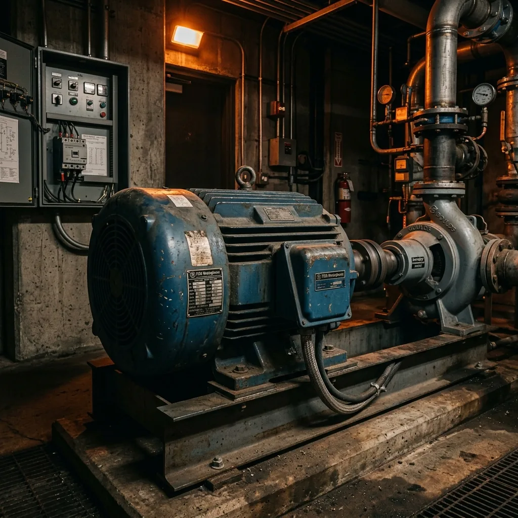
| Fan and pump duty | Airflow, static pressure, water flow and head must align with the distribution design—not only the thermal load. |
| Redundancy and staging | Critical areas, future phases and maintenance strategy may justify modular or standby capacity. |
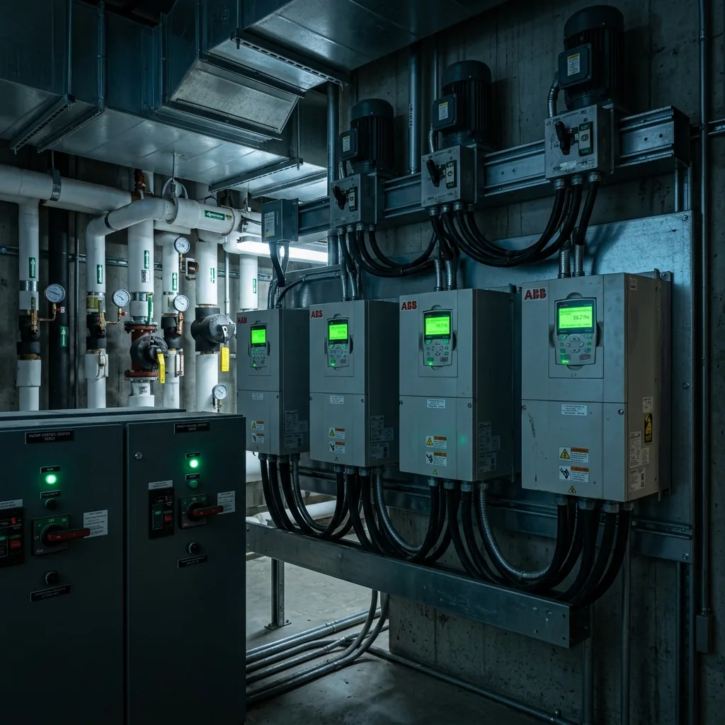
| Electrical coordination | Scheduled voltage, MCA/MOCP, motor/VFD data, disconnects, standby power and controls must be coordinated with the electrical design. |
| Space and serviceability | Clearances, access, acoustic limits, shaft sizes, roof loading and replacement routes can govern the practical selection. |
For more detail on the interface between equipment schedules and electrical design, see HVAC Electrical Coordination: Motor Controls, VFDs and Mechanical Coordination.
Oversizing has consequences
Adding multiple undocumented safety factors can create unrealistic capacity. Oversized equipment can short-cycle, reduce dehumidification, increase capital and electrical infrastructure costs, and operate inefficiently. Undersizing can compromise comfort, pressurization, process conditions and recovery. The defensible approach is to document uncertainty once, then apply justified selection allowances and project criteria.
Ontario Code and Energy Context
Ontario's 2024 Building Code came into effect on January 1, 2025. HVAC design is reviewed within the building's occupancy, construction and system context, including applicable Part 6 provisions and energy-efficiency requirements such as SB-10 where relevant. Municipal submission requirements and the standards referenced by the Code also need to be confirmed for the actual project.
ASHRAE load-calculation methods provide an engineering basis for determining loads; they do not replace an Ontario code analysis. Likewise, residential heat-loss/heat-gain procedures should not be carried into a commercial project without confirming scope and applicability.
A compliant submission is more than a software report. It should make the building assumptions, calculation method, design conditions, zoning, ventilation basis, system configuration and equipment-selection logic reviewable.
A Defensible HVAC Load-Calculation Workflow
- Define the basis of design. Confirm occupancy, operating schedules, indoor criteria, weather data, resilience objectives, code path and project stage.
- Build and verify geometry. Coordinate floor areas, orientations, envelope assemblies, glazing and zoning with architectural information and site conditions.
- Document internal and outdoor-air inputs. Record people, lighting, equipment, process, ventilation, exhaust, infiltration and diversity assumptions.
- Calculate hourly zone loads. Separate sensible and latent components and identify the time and driver of each zone peak.
- Develop system and plant loads. Preserve coincidence and add system effects such as fan heat, duct gain/loss, heat recovery and distribution losses in the correct location.
- Select and coordinate equipment. Use performance data at project conditions, then coordinate airflow, hydronics, controls, acoustics, structure, space and electrical requirements.
- Issue a traceable deliverable. Provide assumptions, input summaries, zone/system reports, selection schedules, limitations and unresolved coordination items.
What a useful deliverable includes
- Design weather, indoor conditions and calculation method.
- Envelope, occupancy, lighting, equipment and schedule assumptions.
- Ventilation, exhaust, infiltration and heat-recovery basis.
- Zone heating, sensible cooling and latent cooling results with peak times.
- System/block load summary and explanation of diversity.
- Equipment selections at project conditions and the applied sizing rationale.
- Mechanical, electrical, controls, architectural and structural coordination notes.
Technical References
- 2025 ASHRAE Handbook—Fundamentals, Chapter 18: Nonresidential Cooling and Heating Load CalculationsPrimary source for load components, calculation methods, zone/system distinctions, design conditions and treatment of heating and cooling loads.
- ASHRAE Standards—Titles, Purposes and ScopesOfficial scope information for ANSI/ASHRAE Standard 62.1 and other standards referenced during HVAC design.
- Ontario Regulation 163/24Adopts the 2020 National Building Code with Ontario amendments as the 2024 Ontario Building Code.
- Ontario Building Code UpdatesOfficial effective-date and transition information for the 2024 Ontario Building Code.
- Ontario Building Services SyllabusIdentifies Part 6 building-services and SB-10 energy-efficiency subject areas in the 2024 Code framework.
Frequently Asked Questions
What is the difference between a zone load and a block load?
A zone load is the heating or cooling demand of one control zone at a stated time. A block load is the coincident load of the building or system served. Because zones often peak at different times, the block peak is not normally the sum of every zone's individual peak.
Can HVAC equipment be sized from floor area alone?
Floor-area rules of thumb can be useful for early screening, but they do not replace a project-specific calculation. Envelope performance, orientation, glazing, occupancy, process loads, outdoor air, schedules and zoning can materially change the result.
Does the calculated peak load equal the equipment capacity to select?
Not automatically. Equipment selection also considers sensible and latent capacity, entering conditions, ventilation, fan heat, heat recovery, manufacturer performance data, part-load operation, redundancy and applicable sizing allowances.
Which Ontario requirements should be checked with an HVAC load calculation?
The project team should verify the current Ontario Building Code, applicable Part 6 requirements, SB-10 where applicable, referenced standards, municipal requirements and the actual occupancy and building scope. ASHRAE methods support the engineering calculation but do not replace jurisdictional review.
Planning HVAC Load Calculations?
ETEM can review existing mechanical systems, proposed equipment and coordination requirements to help define a practical project scope.
Planning an HVAC Upgrade or Fit-Out?
ETEM Engineering coordinates commercial heating and cooling load calculations, equipment selection, electrical interfaces and construction-ready documentation across Ontario.
Discuss Your Building