Motor Protection Essentials: MCA, MOP & How to Size Them
Every HVAC unit, pump, and compressor on a building has a nameplate. On that nameplate, two critical values determine how you design the electrical circuit: MCA and MOP. Get them wrong, and you're either tripping breakers on startup or leaving equipment unprotected.

What is MCA (Minimum Circuit Ampacity)?
MCA stands for Minimum Circuit Ampacity. It defines the minimum current-carrying capacity that the wire and other circuit components must have. The wire you select must have an ampacity equal to or greater than the MCA value on the equipment nameplate.
How MCA is Calculated
For a single motor, the Canadian Electrical Code (CEC) Rule 28-106 defines:
MCA = 125% - FLC (Full Load Current) of the largest motor + 100% - FLC of all other motors + 100% of any heater loads
The 125% multiplier accounts for the continuous duty rating of motor circuits - motors are expected to run at full load for extended periods, and the wire must handle this thermal load safely.
Practical Example
Consider a rooftop unit (RTU) nameplate showing:
- Compressor: 28A FLC
- Supply fan motor: 8A FLC
- Electric heater: 15A
MCA = (125% - 28) + 8 + 15 = 35 + 8 + 15 = 58A
You must select a wire with ampacity 58A. Per CEC Table 2, this means #6 AWG copper (65A) in typical conditions.
What is MOP (Maximum Overcurrent Protection)?
MOP stands for Maximum Overcurrent Protection. It defines the maximum size of the circuit breaker or fuse protecting the circuit. You must select a breaker equal to or less than the MOP value.
How MOP is Calculated
Per CEC Rule 28-200, for motor circuits:
MOP = Maximum percentage of FLC (per CEC Table 29) for the largest motor + 100% - FLC of all other motors + 100% of heater loads
The maximum percentage depends on the protective device type and motor type:
| Protection Device | Squirrel Cage Motor | Wound Rotor Motor |
|---|---|---|
| Non-time-delay fuse | 300% | 150% |
| Time-delay fuse | 175% | 150% |
| Inverse-time circuit breaker | 250% | 150% |
| Instantaneous-trip breaker | 800% | 800% |
Continuing Our Example
Using an inverse-time circuit breaker (most common):
MOP = (250% - 28) + 8 + 15 = 70 + 8 + 15 = 93A
Round down to the next standard breaker size: 90A breaker.
Critical Rule: If the MCA requires #6 AWG wire (65A ampacity) but the MOP allows up to a 90A breaker, this is normal and correct. Motor circuits are the exception to the general rule that the breaker must not exceed wire ampacity. The motor's internal overload relay provides the running overcurrent protection.
Common Motor Protection Selection Table
The following table provides quick reference values for standard three-phase motors at 208V and 460V, using inverse-time circuit breakers:
| Motor HP | FLC @ 208V | MCA @ 208V | Wire Size | MOP (Breaker) | FLC @ 460V | MCA @ 460V |
|---|---|---|---|---|---|---|
| 1 | 4.6A | 5.75A | #14 | 15A | 2.1A | 2.6A |
| 2 | 6.8A | 8.5A | #14 | 20A | 3.0A | 3.75A |
| 3 | 9.6A | 12A | #14 | 25A | 4.2A | 5.25A |
| 5 | 16.7A | 20.9A | #10 | 45A | 7.6A | 9.5A |
| 7.5 | 24.2A | 30.3A | #8 | 70A | 11A | 13.75A |
| 10 | 30.8A | 38.5A | #8 | 80A | 14A | 17.5A |
| 15 | 46.2A | 57.8A | #6 | 120A | 21A | 26.25A |
| 20 | 59.4A | 74.3A | #4 | 150A | 27A | 33.75A |
| 25 | 74.8A | 93.5A | #3 | 200A | 34A | 42.5A |
| 30 | 88A | 110A | #1 | 225A | 40A | 50A |
| 40 | 114A | 142.5A | #1/0 | 300A | 52A | 65A |
| 50 | 143A | 178.8A | #3/0 | 400A | 65A | 81.25A |
Note: Values are approximate and based on CEC Table 44/45 FLC values for standard NEMA B design motors. Always verify with the actual equipment nameplate and local code edition.
The Role of the Overload Relay
The circuit breaker (MOP) protects against short circuits and ground faults. It does not protect the motor from overloads. That job belongs to the overload relay, which is typically:
- Built into the motor starter (contactor + overload)
- Set to 115-125% of the motor FLC
- Trips on sustained overcurrent, protecting against locked rotor and overload conditions
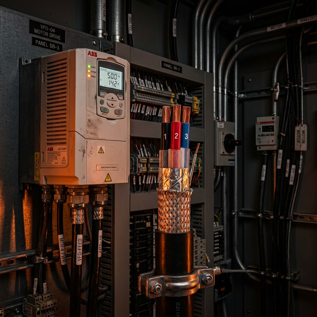
VFD Considerations
When a motor is fed through a Variable Frequency Drive (VFD), the circuit design changes:
- MCA/MOP are based on the VFD input current, not the motor FLC
- VFD provides electronic motor overload protection internally
- Requires VFD-rated cable on the output side to handle high-frequency switching
- Line reactor or input filter may be required to limit harmonic distortion
Frequently Asked Questions
What is MCA and MOP?
MCA = 125% of motor FLA (wire sizing). MOP = max breaker size (typically 250% FLA). See our voltage drop guide for long motor runs.
How do you size wire and breaker?
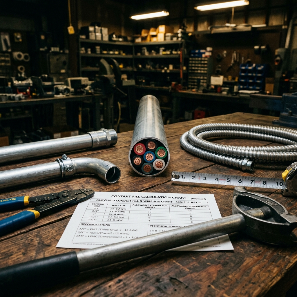
Wire: MCA (125% FLA from CEC Table 44/45). Breaker: max MOP (250% FLA inverse-time). Use conduit fill tables for raceway sizing.
Do VFDs change protection requirements?
Yes. VFDs provide built-in overload protection. Input side still needs branch circuit protection. See our VFD cable guide.
Download the Motor Protection Quick Reference
Get our MCA/MOP calculation worksheet as a printable PDF - free for engineers and contractors.

Need HVAC Electrical Coordination?
Our P.Eng team provides complete motor control design, disconnect integration, and feeder sizing for HVAC equipment of any scale.
Get a Free Consultation