LSI vs LSIG Circuit Breakers: Coordination, Fault Current & Ontario Code
LSI and LSIG are not breaker sizes. They describe the protection functions inside an electronic trip unit. The distinction matters when coordinating upstream and downstream devices, evaluating available fault current, and applying Ontario's ground-fault protection requirements.
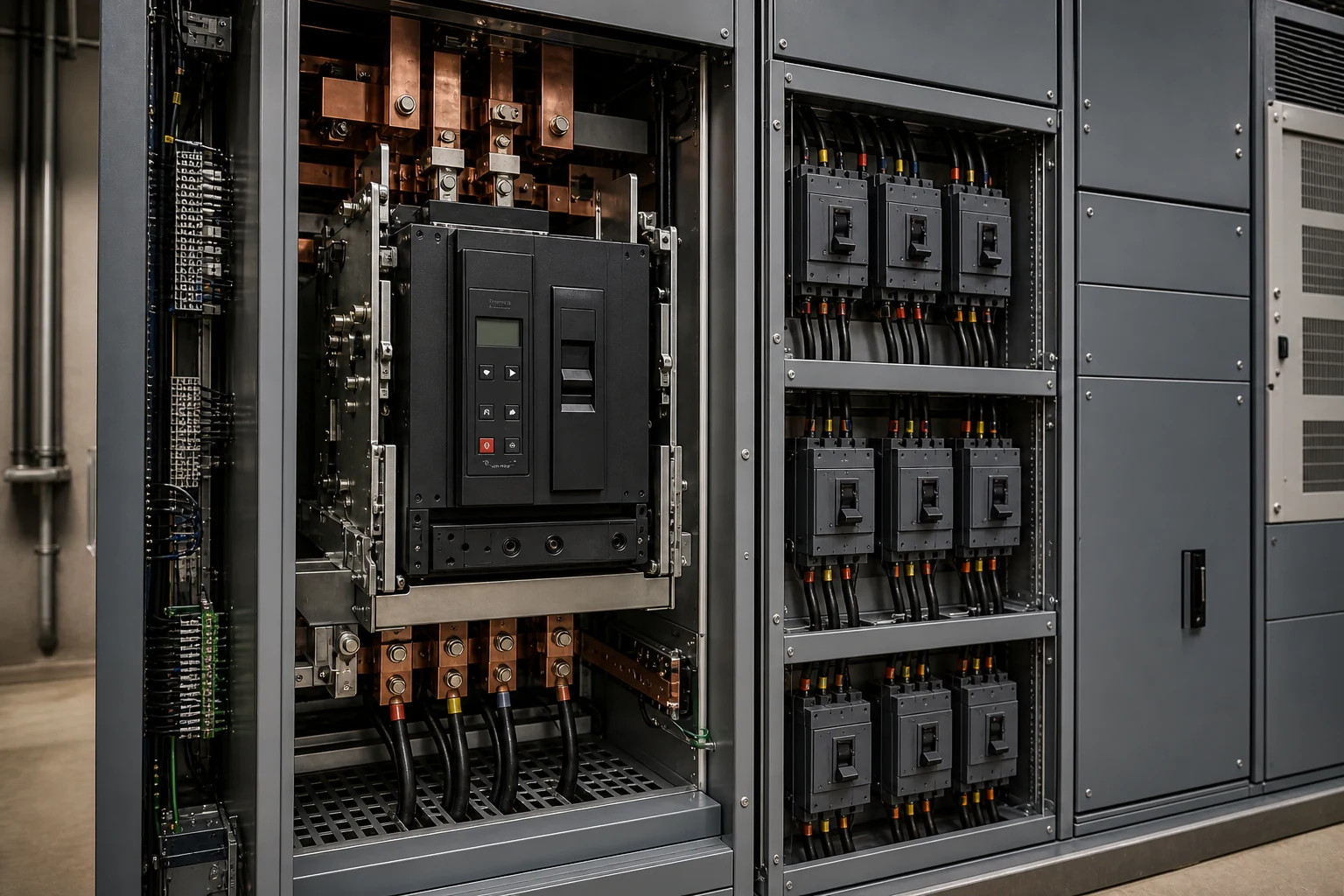
Long-time, short-time and instantaneous functions, with settings that depend on the exact trip unit.
The G function is not the same as a Class A GFCI used for personnel protection.
Ontario's rule includes a 1000 A threshold and a separate 2000 A threshold, depending on system voltage-to-ground.
The Four Trip Functions
Electronic trip units measure current through sensors and apply a programmed protection characteristic. The letters identify available functions—not universal setting ranges. Pickup values, delay bands, I²t options, instantaneous override behaviour and short-time withstand capability must be taken from the selected manufacturer's data.
Long-time
Protects conductors and equipment from sustained overloads. It has an inverse-time response: the greater the overload, the shorter the operating time.
Short-time
Responds to higher overcurrents with an intentional delay, allowing a downstream device time to clear a fault first. Some trip units offer fixed-time or I²t delay shapes.
Instantaneous
Trips without intentional delay above its pickup. It limits fault duration but can defeat selectivity when upstream and downstream instantaneous regions overlap.
Ground fault
Detects equipment ground-fault current using the breaker trip unit and its sensing scheme. It must be coordinated with downstream phase and ground-fault protection.
Ground-fault protection must be applied where required and engineered as a system. A poorly coordinated G function can trip the main before the feeder device. Conversely, disabling instantaneous protection without confirming the breaker's short-time rating and instantaneous override can create an unsafe design.
How to Read a Time-Current Curve
A time-current curve (TCC) uses logarithmic axes: current increases to the right and operating time decreases toward the bottom. The plotted band—not a single line—accounts for device tolerances. Loads, transformer inrush, motor-starting curves and conductor or equipment damage limits are normally overlaid with the protective-device bands.
Conceptual LSI operating characteristic
Long-time, short-time and instantaneous regions shown on normalized log-log axes.
What the curve is telling you
| Region | Design question | Common check |
|---|---|---|
| Long-time | Will the breaker carry the design load yet protect the conductor and equipment? | Load current, conductor ampacity, equipment rating and overload margin. |
| Short-time | Can the upstream device wait for the downstream breaker to clear? | Pickup separation, delay, I²t setting and short-time withstand rating. |
| Instantaneous | Do the devices enter competing instantaneous regions? | Available fault current and manufacturer selectivity tables. |
| Ground fault | Will the closest ground-fault device clear first? | Sensor arrangement, pickup, delay, neutral path and downstream phase protection. |
Selective Coordination: Separation to the Available Fault Current
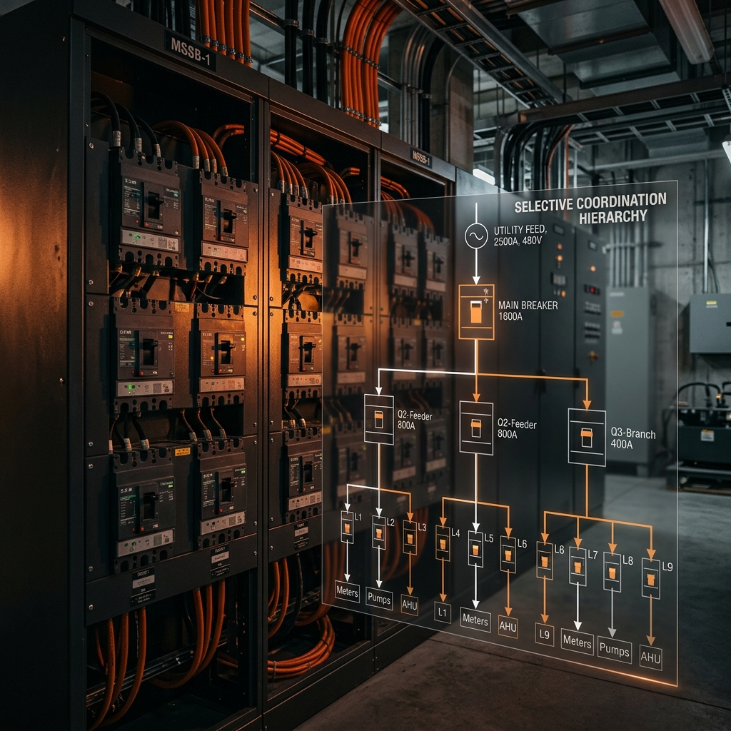
The objective is simple: for a fault on a downstream circuit, the downstream protective device operates while upstream devices remain closed. The proof is more nuanced. Curves should be separated through the range where TCCs are valid, and the result must be checked against the calculated available short-circuit current at the downstream bus.
Illustrative coordinated breaker pair
The downstream band remains left and below the upstream band up to the marked available fault current.
Where studies commonly go wrong
- Comparing breaker frame or handle ratings instead of exact catalog numbers, trip units and settings.
- Checking only the overload region and ignoring instantaneous operation at the downstream bus fault level.
- Assuming that an adjustable instantaneous function can always be turned off.
- Coordinating G only with another G function while ignoring downstream phase overcurrent devices.
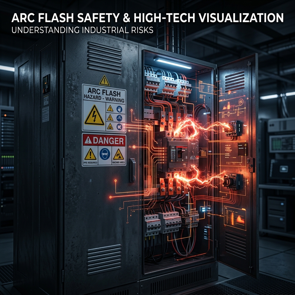
- Adding delay for selectivity without re-running the arc-flash study; longer clearing time can increase incident energy.
Compatible trip units exchange a restraint signal. A downstream device can retain its intentional delay while an upstream device trips quickly for a fault in its own zone, improving fault clearing without abandoning coordination. The complete manufacturer's ZSI scheme—not just the trip-unit label—must be designed and commissioned.
Ontario: What Rule 14-102 Actually Requires
Ontario's current Code is the 29th edition/2024 OESC, effective May 1, 2025. OESC Rule 14-102 addresses ground-fault protection on specified solidly grounded circuits. Its two principal current thresholds are:
Applies, for example, to a qualifying 600Y/347 V or 480Y/277 V solidly grounded circuit.
Applies, for example, to a qualifying 208Y/120 V solidly grounded circuit.
Rule 14-102 also limits the protection setting and delay: subject to the coordination scheme permitted by the Rule, the maximum setting is 1200 A and the maximum delay is 1 s for ground-fault currents of 3000 A or more. The full Rule, Diagram 3, Appendix B notes and any current ESA bulletin must be reviewed for the actual installation.
Important distinction: the OESC requires a ground-fault protection outcome. It does not say that every qualifying installation must use a breaker whose catalog suffix is “LSIG.” An integral G function, external relay and sensor scheme, or coordinated switchgear arrangement may be used when it satisfies the Code and product requirements.
Ground-fault protection is not a GFCI
The G in LSIG is equipment ground-fault protection at distribution-system current levels. A Class A GFCI is a different protective function intended for personnel protection at milliampere levels. The terms should not be used interchangeably on drawings or specifications.
Available Short-Circuit Current Comes First
Coordination cannot be evaluated without the available short-circuit current (ASCC) at each bus. The utility source, transformer impedance, conductor length and size, motors and generators can all affect the result. The interrupting rating of each overcurrent device and the short-circuit rating of the equipment must be suitable for the fault current at its location.
Start With the Serving Electricity Distributor (LDC)—not an Assumed Fault Level
In Ontario, the formal industry terms are electricity distributor and local distribution company (LDC). “Local hydro company” is common plain-language wording for the same organization. Before completing the model, submit a technical inquiry or service-connection request to the serving LDC. The requested utility value is the available fault current or source impedance at a clearly defined point of supply. SCCR is not the number the utility supplies; it is an equipment rating that the calculated fault current is checked against.
An infinite-bus calculation remains useful as a conservative screening case, especially before utility data are available. It should not automatically become the only source case in the final short-circuit, coordination or arc-flash model. Use the LDC's stated current or impedance, the applicable normal and alternate configurations, and any identified future-maximum condition; retain the infinite-source case only where the study basis requires it.
Information to request from the LDC
- Maximum three-phase symmetrical RMS fault current at the point of supply, with the exact voltage and reference location.
- Maximum single-line-to-ground (SLG) fault current at the same point, where available. It supports equipment ground-fault protection and relay sensitivity/coordination studies; it is not, by itself, a complete grounding-system or conductor-sizing study.
- Minimum fault current when protection sensitivity, ground-fault operation or minimum arcing-current cases are being studied.
- Source X/R ratio or available asymmetrical/peak-duty information, if the utility can provide it. X/R affects DC offset, first-cycle peak current and momentary/close-and-latch duty.
- Utility transformer data—kVA, voltage ratio, connection and nameplate or guaranteed impedance—when the service transformer is utility-owned.
- System configuration and basis: normal/alternate feeds, parallel transformers, open or closed ties and whether the value represents current or planned maximum conditions.
- Project identification: service address, account or service reference, requested service size/voltage, one-line diagram and the point where the data will be applied.
Copy the LDC fault-data request template
Adapt this wording to the serving utility's process and attach the one-line diagram and service information.
Subject: Fault Current Data Request — [Project / Service Address]

Hello,

For our short-circuit and coordination study, please provide the following at [point of supply / PCC] at [nominal voltage]:

1. Maximum three-phase symmetrical RMS fault current;
2. Maximum single-line-to-ground fault current, if available;
3. Source X/R ratio and minimum fault current, if available;
4. Utility transformer kVA, ratio, connection and impedance, if applicable;
5. Applicable system configuration and present/planned maximum basis.

Please identify the exact reference point and voltage for the supplied values.

Thank you,
[Name / company / contact information]
Calculate downstream ASCC from the LDC source data, then verify that each breaker's interrupting rating and each assembly's SCCR or withstand rating are not less than the available fault current at that equipment. A tested and approved series combination is a separate application and must be documented as such.
Transformer-terminal screening: this is the infinite-source case. It is useful for a first maximum estimate, but a finite utility source, upstream transformer and feeder impedance reduce the fault current delivered to the next bus.
Worked Fault-Level Examples
The calculation workflow below is adapted from a project fault-level sheet with project identifiers removed. It separates transformer contribution, upstream-source impedance and a simplified rotating-motor contribution instead of treating every bus as an infinite source.
Case A · Transformer-limited screening
Infinite upstream source; fault at the 600 V transformer secondary bus.
Case B · Finite utility source
Actual upstream fault level plus transformer impedance at the 208 V bus.
Transformer-limited fault
- Transformer
- 1000 kVA
- Secondary voltage
- 600 V
- Nameplate impedance
- 5.4%
- Impedance case used
- 5.4% × 0.90
- Full-load current
- 962.3 A
- Transformer contribution
- 19.80 kA
- Simplified motor contribution
- 2.69 kA
Source plus transformer impedance
- Upstream ASCC
- 19.54 kA @ 480 V
- Transformer
- 75 kVA
- Voltage ratio
- 480 / 208 V
- Nameplate impedance
- 7.9%
- Full-load current
- 208.2 A
- Secondary fault current
- 2.75 kA
- Simplified motor contribution
- 0.583 kA
How the finite-source calculation works
SSC,source = √3 × Vprimary × ISC,upstream
Zsource,pu = transformer MVA ÷ SSC,source
Ztotal,pu = Zsource,pu + Ztransformer,pu
ISC,secondary = IFL,secondary ÷ Ztotal,pu
The worksheet applies 90% of nameplate transformer impedance for a conservative minimum-impedance case and estimates motor contribution as 4 × full-load current × motor-load fraction. Those are screening assumptions—not universal Code formulas. Confirm transformer tolerances and model motors from actual data for a final short-circuit, equipment-duty or arc-flash study.
Downstream fault current will usually be lower because conductor and system impedance are added. Conversely, rotating-machine contribution and alternate operating configurations may raise the first-cycle duty at some buses. Study the credible source configurations rather than using a single transformer calculation everywhere.
A Defensible Study Workflow
- Build the one-line and source cases. Confirm utility data, transformer kVA and impedance, conductor lengths, generators, motors and tie states.
- Calculate ASCC at every relevant bus. Use the appropriate symmetrical and asymmetrical duties for the equipment being checked.
- Verify protection and equipment ratings. Check interrupting ratings, equipment short-circuit ratings, conductors and any approved series combinations.
- Enter exact device data. Model catalog number, frame, sensor/rating plug, trip unit, pickup, delay, I²t choice, instantaneous override and ground-fault sensing method.
- Overlay TCCs and equipment limits. Include loads, motor starting, transformer inrush and damage, conductor damage and the maximum available fault current.
- Check manufacturer selectivity tables. Use tested data where curves enter the instantaneous or current-limiting region.
- Re-run arc-flash and document settings. Coordination, equipment protection and incident energy must be evaluated together. Issue a setting schedule and commission the installed scheme.
Technical References
The following primary sources support the Code edition, Ontario thresholds and the engineering principles used above. Manufacturer documents are application guidance; they do not replace the OESC or project-specific engineering.
- Electrical Safety Authority — Ontario Electrical Safety CodeConfirms the 29th edition/2024 OESC and May 1, 2025 effective date.
- ESA Bulletin 10-22-5 — Delta-to-wye conversion requirementsOfficial ESA bulletin restating Rule 14-102 thresholds for solidly grounded systems.
- ESA Bulletin 2-11-27 — Plans and specificationsIdentifies ground-fault protection design information required for plan review where multiple sources exist.
- Schneider Electric — Electrical Distribution Fundamentals: System ProtectionElectronic trip functions, TCC coordination, short-time delay and instantaneous override.
- Schneider Electric — Zone-selective interlockingManufacturer guidance for short-time and ground-fault ZSI operation.
- Eaton — Circuit breaker time-current curvesManufacturer TCC library for exact product data.
- Eaton — Selective Coordination Breaker ApplicationExplains tested breaker-pair selectivity tables and their relationship to TCCs.
- IESO — Find Your Local Distribution CompanyDefines local electricity utilities as local distribution companies (LDCs) and identifies the distributor serving each Ontario service area.
- Toronto Hydro — Service connection requestsOfficial route for new services, upgrades and other connection work; the applicable LDC process varies by service territory.
- Toronto Hydro — Metering Requirements, 750 V or LessRequires service equipment short-circuit and interrupting ratings to be sufficient for the maximum available fault current.
- Hydro One — Connection and customer contactsContact route for customers in Hydro One's service territory; large and specialized connections may be routed to dedicated teams.
Frequently Asked Questions
Does a 1000 A breaker always need LSIG in Ontario?
No. Rule 14-102 depends on system grounding and voltage. A qualifying solidly grounded circuit above 150 V to ground and below 750 V phase-to-phase reaches the threshold at 1000 A or more. At 150 V or less to ground, the threshold is 2000 A or more. The required protection can also be implemented by a compliant scheme other than an integral LSIG trip unit.
Can I turn off instantaneous protection to achieve coordination?
Only if the selected breaker and trip unit permit it and the application stays within the manufacturer's short-time withstand and instantaneous override limits. The effect on equipment protection and arc-flash incident energy must also be checked.
Why can manufacturer tables show coordination when TCC bands overlap?
At very short operating times, current limitation and the dynamic interaction of two breakers are not fully represented by conventional TCC plots. Tested manufacturer tables can document selectivity for the exact device pair up to a stated fault-current value.
Is the G function the same as a receptacle GFCI?
No. The G function is equipment ground-fault protection in a distribution breaker. A Class A GFCI is personnel protection operating at milliampere-level leakage current.
Get Technical Insights Delivered
Power systems, protection coordination and Ontario code compliance—engineering insights from our P.Eng. team.
Need a Short-Circuit or Coordination Study?
ETEM Engineering prepares short-circuit, protection-coordination and arc-flash studies for commercial, institutional and industrial facilities.
Discuss Your System