Short Circuit & Selective Coordination Explained
A fault in one branch circuit should not black out an entire floor. That's the promise of selective coordination - and delivering on it requires more than just picking the right breaker sizes. It requires understanding how overcurrent devices interact under fault conditions.
What is a Short Circuit?
A short circuit occurs when current finds an unintended low-resistance path - typically phase-to-phase or phase-to-ground - bypassing the normal load. The result is a massive surge of current, limited only by the source impedance of the system. In a typical commercial building, available short circuit current (ASCC) at the main panel can range from 10,000A to 85,000A - far beyond what any normal load ever draws.
The Two Types of Overcurrent Events
| Type | Magnitude | Cause | Device Response |
|---|---|---|---|
| Overload | 110-600% FLA | Too much load, motor stall | Thermal trip (time-delay) |
| Short Circuit | 1,000-100,000% FLA | Wiring fault, insulation failure | Magnetic trip (instantaneous) |
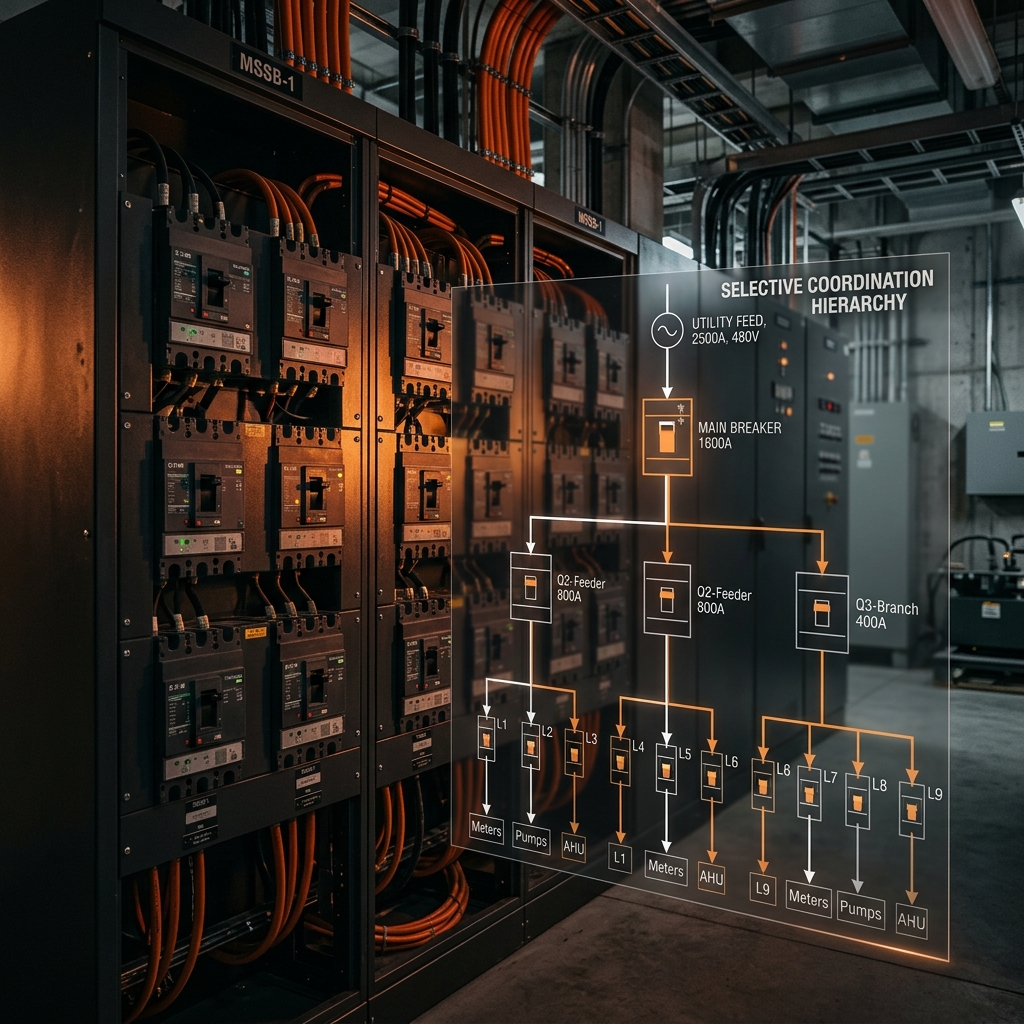
What is Selective Coordination?
Selective coordination means that when a fault occurs, only the overcurrent device immediately upstream of the fault operates - while all upstream devices remain closed. The rest of the system stays energized.
"Without selective coordination, a fault on a single 20A branch circuit could trip the 400A main breaker, blacking out the entire floor. With selective coordination, only the 20A breaker trips. This is not just a convenience - in hospitals and emergency systems, it's a life-safety requirement."
Why Coordination Fails
The most common reason coordination fails: two series breakers both have instantaneous trip regions that overlap. When a large fault current flows, both devices "see" a fault above their instantaneous trip threshold and race to open. The upstream device - being physically larger - often wins, causing an unnecessary upstream outage.
The Time-Current Curve (TCC)
The foundation of coordination analysis is the Time-Current Curve - a log-log plot showing how long it takes a protective device to trip at various fault current levels. For two devices to be coordinated, their TCC curves must not overlap across the full range of available fault current.
Key zones on a TCC:
- Overload region (1-10" rated): thermal curves; time-delay zone where separation is achievable
- Short-time delay region (10-20"): zone where LSIG-type breakers can hold for 0.1-0.4s
- Instantaneous region (high fault current): the challenging zone where most coordination failures occur
Breaker Types and Their Coordination Capability
| Breaker Type | Trip Functions | Coordination Capability | Typical Use |
|---|---|---|---|
| Standard MCB | Thermal + Magnetic (fixed) | Limited - fixed instantaneous | Branch circuits |
| Molded Case (MCCB) | Thermal-magnetic adjustable | Moderate | Sub-panels, feeders |
| LSIG Electronic | Long-delay, Short-delay, Instantaneous, Ground fault | Excellent - programmable delays | Main service, large feeders |
| Current-Limiting Fuse | Melts before peak current | Excellent - inherently fast | Downstream of large breakers |
LSIG Breakers: The Coordination Workhorse
For main service and large feeder applications, LSIG electronic trip units are the standard tool for achieving selective coordination. The four adjustable functions provide the flexibility to separate trip curves:
-
L
Long-delay (overload): Pickup typically 0.4-1.0" In, with adjustable time delay (class 10-40). Handles sustained overloads.
-
S
Short-delay: Pickup typically 2-10" In, with intentional time delay of 0.1-0.4s. This is the key function for coordination - it allows downstream devices to clear faults first.
-
I
Instantaneous: Backup protection for very high fault currents (typically >15" In). Can be set high or disabled when coordination requires it.
-
G
Ground fault: Detects ground fault currents below the phase trip threshold. Critical for equipment protection in solidly-grounded systems.
Available Short Circuit Current (ASCC)
Before any coordination study can begin, the available short circuit current at each point in the system must be calculated. The formula for a three-phase bolted fault:
Three-Phase Fault Current:
ISC = kVA × 1,000 / (√3 × V × Zpu)
Example - 500 kVA transformer, 5% impedance (Zpu = 0.05), 208V secondary:
ISC = 500,000 / (1.732 × 208 × 0.05) = 27,700A
This 27,700A is the available fault current at the secondary of the transformer. All downstream equipment - breakers, bus bars, cables, panels - must be rated to withstand this level.
Where Coordination is Mandatory
The CEC and the Ontario Building Code do not universally mandate selective coordination - but specific applications may require it or make it a project/AHJ expectation:
- Emergency systems - life-safety circuits per CEC Section 46
- Legally required standby systems - fire pumps, emergency lighting
- Hospitals and healthcare - NFPA 99 mandates coordination for essential electrical systems
- Data centers - Tier classifications often include coordination requirements
- High-rise buildings - where a floor outage creates evacuation complexity
Practical Coordination Strategy
A systematic approach for a typical commercial building:
- 1. Calculate ASCC at each distribution point (utility - transformer - main - sub-panels - branch)
- 2. Select LSIG main breaker with short-delay function enabled
- 3. Select sub-panel breakers with adjustable instantaneous set above the branch circuit trip level
- 4. Plot TCC curves for all series devices - verify no overlaps at ASCC
- 5. Verify all equipment AIC ratings exceed the available fault current at that point
- 6. Document the coordination study - required for permit submission on complex projects
Frequently Asked Questions
What is selective coordination?
Only the breaker closest to the fault trips. Upstream breakers stay closed. Critical for arc flash protection and life safety.
Where is coordination mandatory?
Emergency systems, healthcare, elevators, and high-rise buildings per CEC and OBC. See our generator sizing guide.
What is ASCC?
Available Short Circuit Current - the max fault current at any point. Determines breaker interrupting ratings. Calculated from utility data through the distribution system.
Get Technical Insights Delivered
Power systems, protection coordination, code compliance - subscribe for engineering insights from our P.Eng team.
Need a Coordination Study?
Our P.Eng team performs short circuit analysis and selective coordination studies for commercial, institutional, and industrial facilities - with full permit documentation.
Get a Free Consultation