Solar PV Electrical Design Fundamentals: Modules, Strings, Inverters & Safety
A solar PV system is not just a set of panels on a roof. It is a DC power source, an inverter system, a utility interconnection, and a code-regulated electrical installation that must remain safe through normal operation, maintenance, shutdown, and emergency response.
PV Building Blocks
Every grid-connected PV design starts with a simple energy path: sunlight creates DC power at the modules, strings combine that DC power, inverters convert it to AC, and the building or utility grid receives the output through properly rated distribution equipment.
| Element | What It Does | Engineering Check |
|---|---|---|
| PV cell | Produces DC voltage when exposed to light | Part of the listed module assembly, not field-designed individually |
| PV module | Combines cells into a rated panel | Review Voc, Vmp, Isc, Imp, power tolerance, temperature coefficients |
| String | Connects modules in series | Check cold Voc and hot Vmp against inverter limits |
| Array | Combines one or more strings | Check string matching, OCP, conductor ampacity, voltage drop, disconnecting means |
| Inverter | Converts DC to grid-synchronous AC | Confirm certification, MPPT window, input current limits, output connection |
| Disconnects and labels | Support operation, isolation, maintenance, and emergency response | Use DC-rated devices and project-specific markings |
Modules, Strings & Arrays
Series and parallel connections behave differently. A series string increases voltage while keeping current approximately the same. Parallel strings increase available current while keeping voltage approximately the same. That distinction drives inverter selection, conductor sizing, overcurrent protection, combiner design, and shutdown strategy.
The Two Temperature Checks
- Cold open-circuit voltage: PV module voltage rises in cold weather. The string Voc at the site design temperature must stay below the maximum DC voltage rating of the inverter and all connected equipment.
- Hot operating voltage: PV module operating voltage falls in hot conditions. The string Vmp must remain inside the inverter MPPT range so the inverter can track the array efficiently.
For Ontario commercial projects, these calculations should be tied to actual module datasheets, inverter input limits, site temperature assumptions, roof layout, shading, conductor routing, and ESA/utility expectations. The calculation is not complete if it only uses the module nameplate wattage. For the utility and export side of the same topic, see our Ontario solar PV net metering guide.
Inverters & MPPT
The inverter is the electrical bridge between the PV array and the building distribution system. Its design role is larger than DC-to-AC conversion: it also sets the allowable string voltage range, maximum input current, export behavior, anti-islanding response, monitoring capability, and often the practical architecture of the whole system.
MPPT stands for Maximum Power Point Tracking. It is the inverter control function that continuously adjusts the PV array's operating voltage and current so the modules produce the highest practical power available under the current sunlight and temperature conditions.
| Inverter Item | Why It Matters |
|---|---|
| MPPT voltage window | Maximum Power Point Tracking works only when the string operating voltage remains inside the inverter's usable range through expected temperature conditions. |
| Maximum DC voltage | Cold Voc must not exceed the inverter and equipment ratings. |
| Maximum input current | Parallel strings and module Isc values must not exceed input ratings. |
| DC/AC ratio | A modest oversizing ratio may improve economics, but must remain within manufacturer limits and owner expectations for clipping. |
| Anti-islanding | Interactive inverters must stop exporting when the grid is unavailable, according to applicable product standards and utility requirements. |
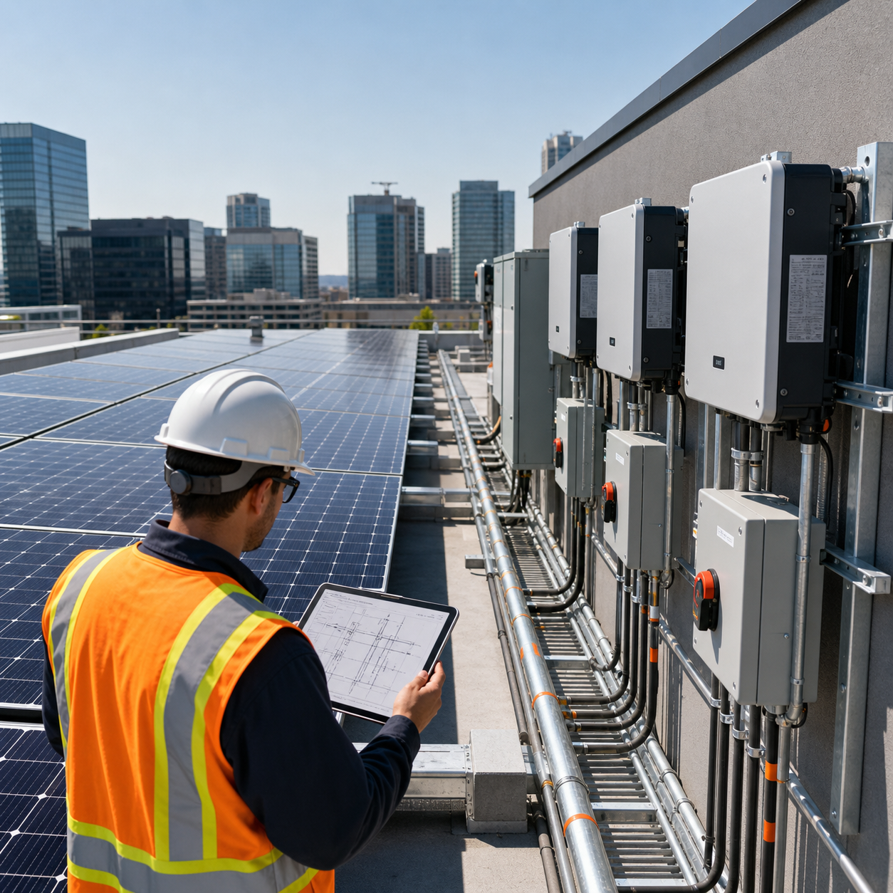
| Environmental rating | Outdoor rooftop locations require appropriate enclosure ratings, working clearances, temperature derating, and service access. |
DC-Side Safety Is Different
PV design is often misunderstood because the rooftop array behaves differently from a normal utility-fed branch circuit. When modules receive light, the DC side can remain energized even after the AC breaker is opened. That changes the design approach for isolation, conductor routing, labeling, maintenance, and emergency response.
- DC arcs are persistent. Use equipment specifically rated for PV DC duty, not AC-only switching devices.
- PV conductors are source conductors. Routing, protection, marking, and disconnecting means need to reflect that they may be energized by the array.
- Shutdown is not always de-energization. Opening one switch may isolate equipment, but modules and short conductor segments can still produce voltage in daylight.
- Labels must be practical. A clear single-line diagram and equipment markings help operators and responders understand multiple power sources.
Protection, Isolation & Marking
IEC-style PV design guides and North American codes agree on the broad engineering goal: prevent unsafe shock, fire, backfeed, overvoltage, and maintenance hazards. The exact rule numbers, product certifications, and inspection expectations are local.
| Design Topic | Good Engineering Practice | Ontario / Canada Note |
|---|---|---|
| Disconnecting means | Provide means to isolate PV sources and interactive equipment for service and emergency response. | Coordinate with OESC/CEC Section 64, equipment instructions, ESA, and the local distribution company. |
| Overcurrent protection | Protect conductors and equipment where parallel sources or backfeed can create overcurrent conditions. | PV source, output, inverter, and interconnection conductors require project-specific review. |
| PV voltage and current ratings | Base circuit ratings on module datasheets, temperature correction, source/output circuit current, and equipment limits. | OESC Section 64 includes PV-specific requirements for maximum circuit voltage, ampere rating, and voltage drop. |
| Surge protection | Assess exposure, conductor routing, equipment sensitivity, and building risk. | Rooftop arrays and long DC runs often justify surge protection coordination. |
| Grounding and bonding | Maintain an effective bonding path for frames, racking, raceways, enclosures, and equipment. | Use CEC/OESC grounding and bonding rules, not generic IEC assumptions. See our grounding vs bonding guide. |
| Wiring method and conductor marking | Keep PV source/output conductors identifiable, protected, and routed for serviceability. | OESC Section 64 has PV-specific wiring method and conductor marking requirements. |
| DC arc-fault, rapid shutdown, and markings | Make energized PV conductors and shutdown functions understandable during emergency response. | Confirm current Section 64 requirements and equipment-specific listing instructions. |
| Utility interconnection | Prevent unsafe backfeed and support stable grid operation. | Local utility requirements, metering rules, export limits, and Section 84 coordination may apply. See our utility connection guide. |
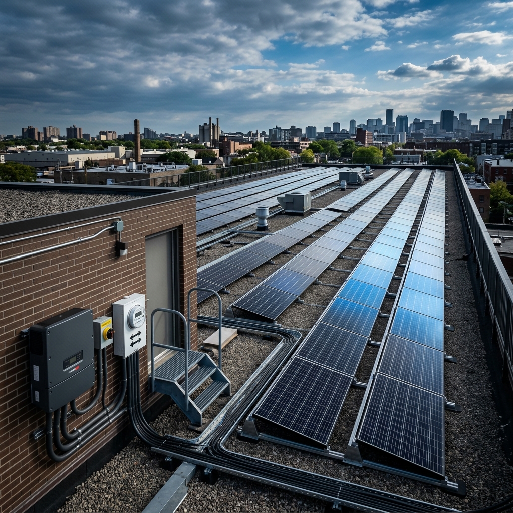
Common PV Architectures
The right PV architecture depends on project size, roof layout, shading, service configuration, utility requirements, maintenance access, and whether the owner wants self-consumption, export, or future storage integration.
| Architecture | Typical Use | Design Watchpoint |
|---|---|---|
| Single string inverter | Small, simple arrays with uniform orientation | Limited flexibility for shading and string mismatch |
| Multiple strings with combiner | Commercial rooftop systems with repeated module groups | Combiner ratings, fusing, disconnects, and conductor routing become critical |
| Microinverters / AC modules | Highly shaded or complex roof layouts | AC branch circuit design, rooftop serviceability, monitoring, and product listing |
| Optimizer-based system | Module-level monitoring and mismatch control | Manufacturer-specific wiring limits and shutdown functions must be followed |
| Self-consumption PV | Buildings that use most PV production on site | Load profile, export limit, metering, and control strategy drive the economics |
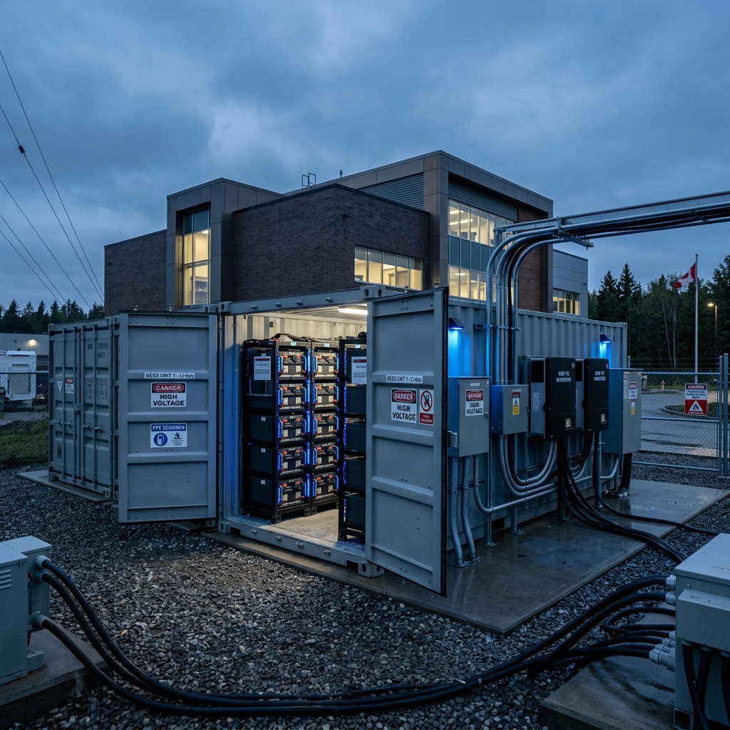
| PV plus BESS | Peak shaving, backup, or energy management | Requires additional review of batteries, fire protection, controls, and interconnection. See our BESS electrical design guide. |
Sizing Checks Engineers Should Not Skip
PV systems fail review when the design jumps from array kW directly to a single-line diagram without proving that the electrical limits work. A professional review should document the following checks:
PV Design Check Sequence:
1. Module datasheet values: Voc, Vmp, Isc, Imp, temperature coefficients
2. Cold-weather string Voc below maximum DC equipment ratings
3. Hot-weather string Vmp inside inverter MPPT range
4. Parallel string current within inverter, conductor, combiner, and OCP ratings
5. AC output connection compatible with service equipment and utility rules
6. Disconnecting means, labeling, grounding, bonding, and shutdown strategy coordinated
IEC vs North America: What Carries Over?
The IEC material is valuable for understanding PV system logic, especially modules, strings, inverters, DC isolation, surge risk, self-consumption, and architecture. The major caution is that an IEC guide is not a Canadian or Ontario code path. It should inform the design thinking, then the actual installation must be checked against North American requirements, including service entrance coordination and voltage drop review where applicable.
| Topic | IEC-Oriented Concept | North America / Ontario Difference |
|---|---|---|
| Core physics | PV cells produce DC power; strings and arrays combine voltage and current. | Same principle. Calculations still depend on module datasheets and site conditions. |
| Primary installation rules | IEC PV installations are commonly framed around IEC 60364 PV guidance. | Ontario uses OESC Section 64 for renewable energy, energy production, storage systems, batteries, and PV-specific rules. |
| Equipment certification | IEC/CE-style product references may appear in global guides. | Use equipment approved for Canada, commonly CSA/cUL/ULC as applicable, and acceptable to ESA/AHJ. |
| Disconnects and switchgear | The engineering need for isolation is the same. | Device ratings, markings, lockability, listing, and locations must satisfy OESC Section 64, Section 84 where interconnected, and utility requirements. |
| Grounding and bonding | System earthing language may differ by IEC supply arrangement. | Use CEC/OESC grounding and bonding terminology and conductor sizing rules. |
| PV circuit ratings | IEC guidance explains source/output circuit behavior and equipment selection concepts. | OESC Section 64 has PV-specific treatment for maximum PV circuit voltage, ampere rating, voltage drop, wiring methods, and conductor marking. |
| DC arc-fault and rapid shutdown | IEC guidance may discuss safety and emergency isolation in general terms. | OESC Section 64 includes PV-specific provisions for DC arc-fault protection, rapid shutdown, and permanent warning markings. |
| Grid interconnection | Connection to the LV switchboard or grid is addressed as an architecture decision. | Interactive inverter outputs are coordinated with OESC Section 84, LDC review, metering requirements, and export rules. |
| Self-consumption | PV production can offset on-site loads before exporting excess energy. | Same business concept, but Ontario economics depend on tariff structure, net metering rules, demand charges, and utility limits. |
Monitoring & Performance Data
For commercial self-consumption projects, monitoring is not a cosmetic dashboard. It proves how much PV production is used on site, how much is exported, whether the inverter fleet is performing, and whether faults are reducing energy value before anyone notices on the utility bill.
Common Design Mistakes
- Using a generic IEC example as if it were an Ontario code design.
- Checking module wattage but not cold Voc, hot Vmp, or inverter input current limits.
- Using AC-rated disconnects, raceways, or labels where PV DC ratings and markings are required.
- Leaving utility interconnection, export limits, or metering coordination until the end of design.
- Ignoring roof access, structural coordination, fire access pathways, and equipment service clearances.
Frequently Asked Questions
Is IEC 60364 applicable to solar PV design in Canada?
IEC-based PV guidance is useful for understanding modules, strings, inverters, isolation, and DC safety. In Canada, it does not replace the Canadian Electrical Code, Ontario Electrical Safety Code, ESA requirements, product certification, or local utility interconnection rules.
What is the most important PV string sizing check?
The string voltage and current must remain within the inverter and equipment ratings across the expected operating temperature range. Cold weather raises open-circuit voltage, while hot weather lowers operating voltage, so both conditions must be checked.
Why are DC disconnects and markings so important in PV systems?
PV conductors can remain energized whenever modules receive light. Disconnects, ratings, labels, and shutdown provisions help installers, operators, and emergency responders understand what can be isolated and what may still be energized.
Download the PV Design Fundamentals Checklist
Get a practical checklist for module data, string sizing, inverter selection, DC isolation, markings, and Ontario interconnection review.
Need Solar PV Electrical Design Review?
ETEM Engineering supports PV projects with string sizing, inverter review, single-line diagrams, OESC/CEC compliance checks, utility coordination, and construction-focused electrical design leadership. For grid-tied export projects, start with our solar PV net metering guide.
Get a Free Consultation